Oszilloscope Clock


Buy by EBay
Turn your XY-capable analogue oscilloscope into a clock.
Simply connect the two channels of your oscilloscope to the X/Y outputs.
Power is supplied via a micro USB socket.
You can choose between 21 different clocks and change them at any time.
The clock continues to run even after the power supply is switched off, thanks to the battery.
An external radio clock module can also be connected to obtain an atomic clock accurate time.
Connection/calibration
Power is supplied via the micro USB socket with a USB power supply/charger.
The oscilloscope is connected to the connection pins marked X and Y and GND.
Switch the oscilloscope to X/Y mode only after connecting it.
In order for the clock to be displayed undistorted, the calibration display must be activated first.
To do this, press S3 repeatedly until it appears.
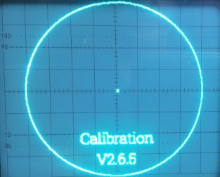
Set both channels of the oscilloscope to 0.2V/div. If probes are used, set them to X1 (not x10).
Use the X-position control and Y-position control of the Y-axis (normally channel 1) to set the middle
point to the centre of the oscilloscope.
Now use the fine adjustment to set the Y-gain to the maximum height (usually 8 fields) and then use the
fine adjustment to set the X-gain to the identical width.
By changing the fine adjustment, the position of the middle point also changes, which must be readjusted
by the position controller.
Repeat this process until you get the picture shown above.
Operation
Pressing S3 continuously switches through all clocks and the calibration display (21 clocks + calibration).
Pressing S1 sets the minutes and S2 sets the hours.
If S1 or S2 are held down, the hours/minutes are changed more quickly.
Furthermore, the second hand (if the currently displayed clock has one) is moved to the 12 o'clock
position and the clock stops.
After setting the time, pressing S3 starts the clock.
DCF77 radio clock input
An external radio clock receiver (DCF77) can be connected to the 4-pole pin strip.
There, 3.3V and 5V are available for the supply of the receiver.
After removing the plug-in bracket, the receiver can be connected to the In pin.
A positive 3.3-5V second pulse must be applied to this pin.
Next to the pin header is an LED that flashes synchronously with the second pulse.
If no receiver is connected, the jumper must be reinserted.
Oscilloscope calibration
Most oscilloscopes have a grid of 8X10 div's, calibration is designed for this.
Since the output voltage of the clock is max. 2.048 volts, both channels of the oscilloscope must be set to 0.2V/div
(corresponds to 1.6 volts on the Y-axis and 2 volts on the X-axis).
These two voltages must therefore first be set exactly.
To do this, proceed as follows:
-
Keep the S3 button permanently pressed. After 2 seconds a test pattern appears, then continue to hold the button down until the test pattern disappears and the "Second" LED flashes.
-
Connect a multimeter (min. 4.5 digits is recommended) to the X output of the clock and set a voltage of 2 volts with the S1 and S2 buttons.
-
Press the S3 button briefly, the DCF-77 LED should now flash.
-
Connect the multimeter to the Y output of the clock and set a voltage of 1.6 volts with the S1 and S2 buttons.
-
Connect your oscilloscope to the clock and switch to XY mode.
-
Press and hold the S3 button until a clock appears - Done.
The watch is now calibrated and you can display the test patterns.
To do this, press and hold the S3 button for 2 seconds until a test pattern appears.
The test patterns can be changed by briefly pressing the S3 button.
To exit the test patterns, keep the S3 button pressed for 2 seconds until a clock is displayed.
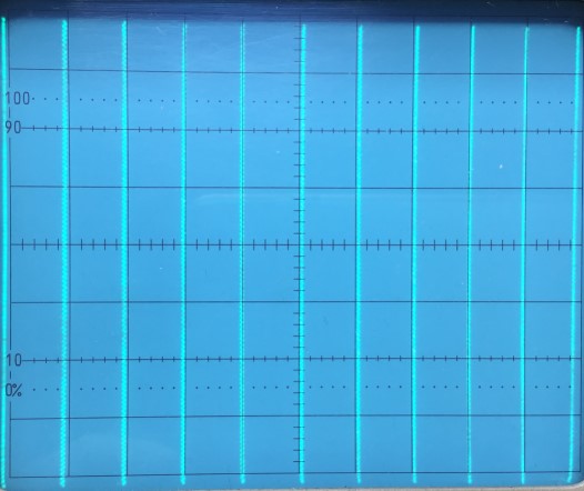
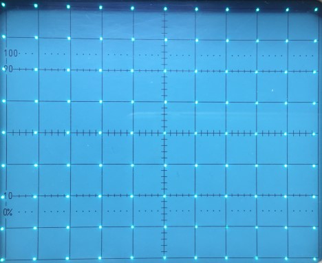
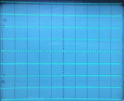
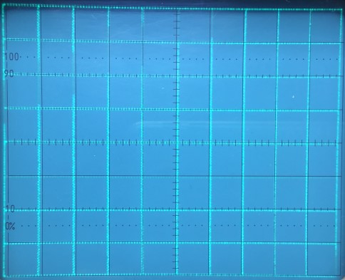
There are 4 test patterns available for calibrating your oscilloscope:
